Methods and experimental techniques
Zakirov I.V., Sretenskaya N.G. Experimental apparatus for hydrothermal investigations.
key words [apparatus hydrothermal]
Experiment in the hydrothermal region field contributes to the solution of a number of problems in the nowadays geochemistry. These problems are: mineral equilibrium with water participation, solubility of substances and minerals in water, water vapor and fluid of simple and complex composition as well as kinetics of the reactions investigated. Naturally, the investigators strive for receiving maximum information in the course of experiments and avoid errors produced by the specific of apparatuses and techniques. Based on the experience of many years,
37
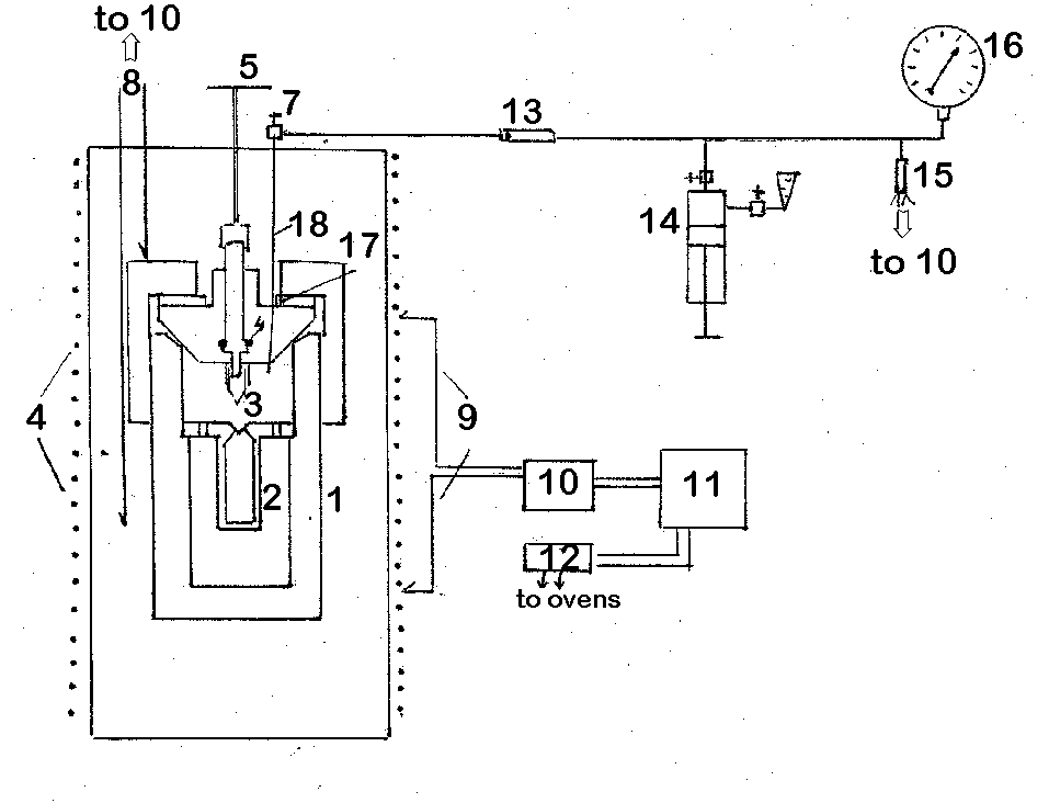
we have designed and built in the Institute of Experimental Mineralogy simple and rather universal apparatus for hydrothermal research in the PT region up to 500oC and 1000 bar. A common scheme of the apparatus is given in Fig.1. It is a reactorI made of titanium alloy BT-8, passivated in nitric acid with the inner volume of about 120 cm3 .
Two types of seal-free valves designed in IEM are used. Fig.1 shows the titanium valve obturation with the washer of the alloy with a higher coefficient of thermal expansion 17. Capsule 2 of BT-8 with the inner volume from1 to 20 cm3 depending on the task posed, is placed inside the autoclave.
The capsule can be locked up at any parameters in the course of experiment with the so called "hot" valve disigned by us. The construction of this valve is shown in Fig.2 in combination with another method of obturation proposed by N.V.Kapustin. The valve sealing is provided by the washer of graphlex 8, adjusted to the valve needle 7 by the sleeve 5 with the nut 9.
The lock needle 4 of the valve is square in cross-section and is connected with the valve needle 7 by means of thread. Thus, the lock needle only moves at the rotation of needle 7 which provides the constant inner volume of the reactor.
Fig.1. Apparatus scheme.
1-reactor, 2-capsule, 3-lock needle, 4-graphite gland, 5-valve gate, 6 - 2 furnaces, 7-microvalve, 8-control thermocouples, 9-regulating thermocouples, 10-interface, 11-computer, 12-block of thiristors, 13-piston separator, 14- press, 15-pressure transduser, 16- pressure gauge, 17-washer, 18-capillary
Fig.2."Hot" valve.
1- reactor body, 2-coupling nut, 3- seal ring, 4- lock needle, 5- sleeve, 6-obturator, 7-valve needle, 8- washer, 9- nut
1-capsule body, 2- valve needle, 3-rubber ring, 4-nut.
Obturation of the reactor is provided with the complex-shaped ring 3, made of the same material as the reactor. It should be noted that such a valve needs no effort at closing and openning of the reactor. A titanium capillary 18 provided with microvalve 7 is welded in the obturator to measure pressure. The capillary allows to supply the reactor with the gas amounts given (for example, CO2, H2) and to make sampling in the course of experiment. For this purpose, a titanium capsule shown in Fig.3 is used. The capsule is connected with the capillary by means of the nut 4 and has itsown microvalve 2. The necessary quantity of gas can be, thus, introduced in the equipped reactor by locking the valve 7 and connecting the capsule. The amount of gas is determined by the weight method with the accuracy of analytical balance. Moreover, the preliminary evacuated capsule can be used in the course of the run for sampling gas phase. Measuring pressure in the reactor is carried out with the pressure gauge 16 and pressure transducer 15 D-100, through the piston separator 13.
The press supports the separator piston providing the minimum useless volume of the pressure measuring system of 0.05 cm3. Control, measuring, and record of temperature and pressure is realized with the specially designed interface connected with the PC II, block of thiristors 12, pressure transducer, and thermocouples. A special software allows to give run parameters, read and record temperature and pressure during the run with the time interval given.
Technique possibilities.
38
The construction proposed allows to eliminate the inevitable errors which appear when introducing the regime and quenching the reactor. For example, at the study of salts solubility in water vapor a solid phase is placed in the capsule 2 and locked by the valve 3. After reaching the run conditions, the valve opens up and the salt comes in contact with gas phase. Before the quenching the valve locks up again. Obviously, the solid phase with water can be, if necessary, placed on the reactor bottom and gas phase can be locked in the capsule 2 at any stage of the run. An outer capsule shown in Fig. 3 permits to organize the fluid of complex composition, for example, H2O-CO2-H2S. A possibility of measuring and recording pressure enables the study of the kineticts of the processes which take place with changing volume. The apparatus described was used for determining KCl solubility in water vapor, AgCl in H2O-CO2 and and for studying phases in the system Al-H2O.
39